- Self-supporting structure with sandwich panels th. 25 mm in internally galvanised sheet and pre-painted externally in RAL 9002 finish
- Non-flammable thermal and acoustic insulation in mineral wool
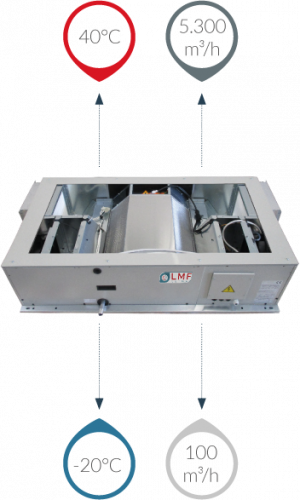
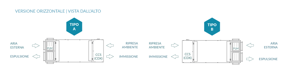
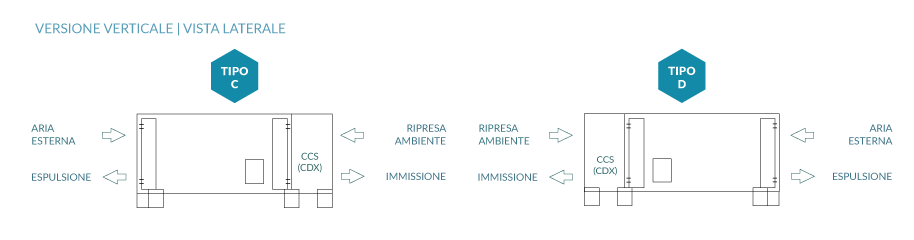
- Static heat recovery unit with very high efficiency (> > 90%) of the counter flow air-to-air type with aluminium exchange plates fitted with additional sealing, integrated with an already motorised by-pass system. Aluminium condensate collection tank, with 1/2” M drain (lateral for horizontal unit, lower for vertical unit)
- Compact filters with synthetic media (external layer) and fiberglass (internal layer) and galvanised steel frame, efficiency class ePM10 50% on room return and ePM1 50% on outdoor air intake, removable at the bottom and side.
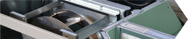
- Centrifugal fans with free-running impeller with backward curved blades directly coupled to EC technology electric motors. Impeller in fiberglass-reinforce
- Recessed type electrical panel with electronic adjustment and remote user interface for complete control of all the key functions and specifically:
- manual control of the EC fans
- automatic control of the fans (for pressure, temperature or air quality)
- modulating control of the water valve (mixed use)
- electric heater management (pre and post)
- recovery unit defrosting management
- free-cooling on/off management
- post-ventilation
- weekly programming
- alarm management and clogged filter warning
- remote on/off
- remote summer/Winter
- fan management via fire alarm digital input
- BMS via Modbus protocol and RS485 connection
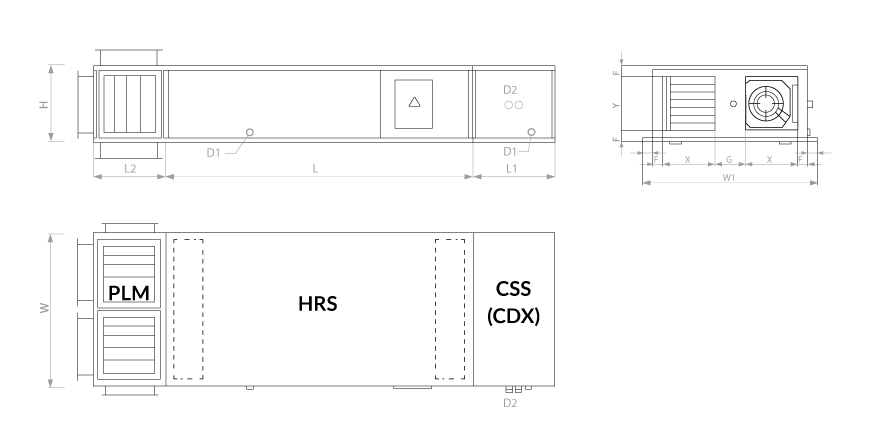
EC fan and high efficiency filter
Damper with actuator and filter removal access door
CCS section with water coil
(1) referred to nominal flow rate
(2) inlet air at 28°C/60%UR; water in/out 7°/12°C
(3) inlet air at 13°C/; water in/out 45°/40°C
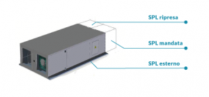
The table shows the sound power values (SWL) in octave and total bands. The sound pressure levels (SPL) at 1m, 5m and 10m in supply, return and outside the unit are also indicated. All values refer to the operation of the ducted unit at MAXIMUM speed and nominal flow rate
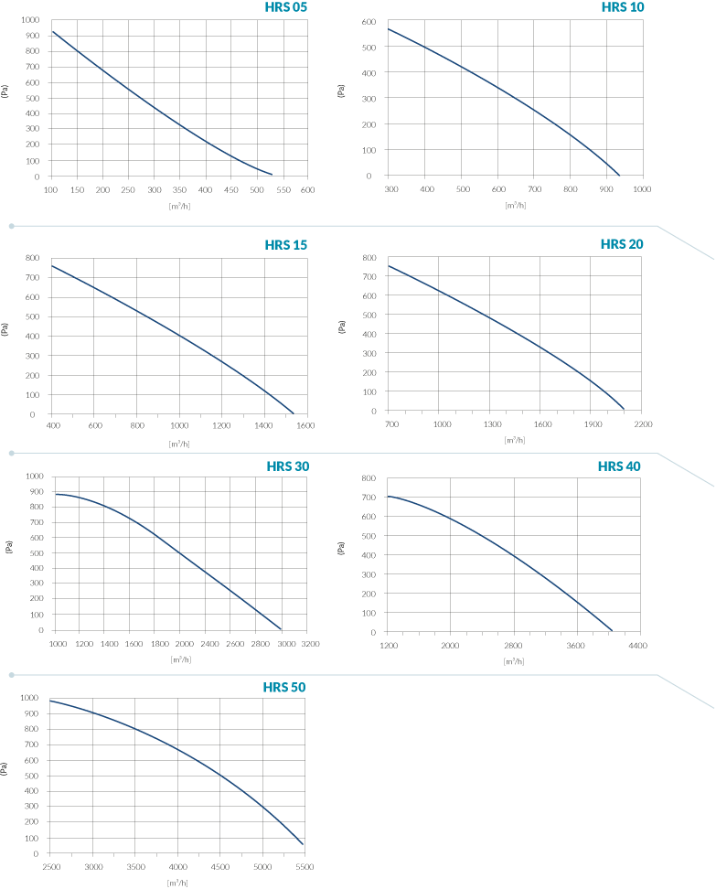
The graphs provide an indication of the useful static pressure (P a) as the airflow [m 3/h] supplied by the base inlet unit varies. Consult the technical bulletin to check the specific data of the unit's aer aulic performance.