- Self-supporting structure with sandwich panels th. 25 mm in internally galvanised sheet and pre-painted externally in RAL 9002 finish
- Filter sections on recirculation air in efficiency class ISO ePM1 50% and ISO ePM10 50% on return air.
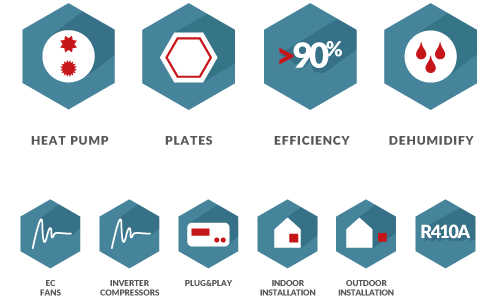
- Fan sections with backward curved blade plug-fans, directly coupled to EC brushless electronic motors.
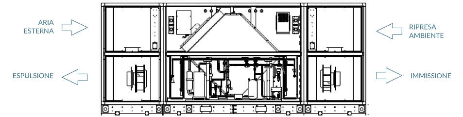
- Static air-to-air flow recovery unit with high efficiency countercurrent flows, Eurovent certified, equipped with aluminium exchange plates complete with bypass damper for free-cooling and modulating servomotor
- Thermodynamic recovery section created with R410A reversible refrigerant circuit, consisting of: EC twin rotary brushless hermetic compressor(s) with dedicated inverter, Cu/Al finned tube evaporator/condenser, electronic expansion valve, cycle reversing valve, high pressure switch, high and low pressure transducers, liquid separators and receivers.
- Electrical panel complete with on-board machine display and microprocessor to manage the temperature set-point in supply, based on operating logics designed to maximise energy savings and environmental comfort, thanks to the modulation of cooling capacity and air flow guaranteed by the inverter technology. The unit is prepared for connection via RS485 to supervision systems based on Modbus RTU/Modbus RTU/RS 485/Modbus TCP/IP protocol; Bacnet TCP; Webserver.

Standard electronic control with graphic display
High efficiency recovery unit with built-in by-pass
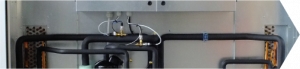
Large compartment outside the airflow for access to the electrical panel and to the refrigerant circuit
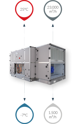
(A) Input temperature ≤ 20°C; balanced air flow rates
(B) Input temperature ≥ 22°C; balanced air flow rates
(1) outdoor air at -10° C 90% RH, ambient air at 22°C 50% RH; nominal air flow rate
(2) outdoor air at 32° C 50% RH, ambient air at 26°C 50% RH; nominal air flow rate
(3) with ventilation regulation signals and heat pump at the maximum permissible value
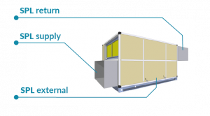
With reference to the nominal operating conditions, the following table shows the sound power values (SWL) in octave band and the related results; the sound pressure values (SPL) at 1m, 5m and 10m in supply, in return and outside of the unit are also highlighted, under ducted unit conditions.
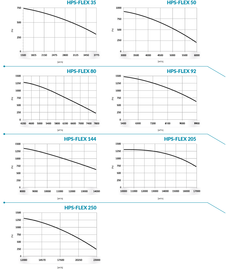
The graphs provide an indication of the useful static pressure (P a) as the airflow [m3/h] [m3/h]supplied by the base inlet unit varies. Consult the technical bulletin to check the specific data of the unit's aeraulic performance.