Product Range

RFH

High efficiency heat recovery unit
WITH MODULATING HEAT PUMP CIRCUIT
and PLATE RECOVERY UNIT
from 300 to 4.000 m³/h

The new RFH heat recovery units dedicated to exchange the air (with the possibility of varying the flow rate) and to its heat treatment (with the possibility of controlling the supply temperature in the rooms) have been designed and developed in order to reconcile many typical needs of both tertiary and commercial applications.
The RFH series consists of 4 sizes in a horizontal configuration only, for air flow rates ranging from 300 to 4000 m3/h.

  • Supporting frame in RAL 9002 pre-painted galvanised sheet metal; Double-shell closing panels with a thickness of 20 mm, in pre-painted galvanised sheet metal RAL 9002 outside and galvanised inside; hinged at the bottom for easy access to the internal components.
  • Non-flammable thermoacoustic insulation in mineral wool with a density of 100 kg/m3.
  • High efficiency static heat recovery unit (>>70% under nominal conditions) of the cross-flow air-air type with aluminium exchange plates with additional sealing; lower condensate collection tank, extended to the entire area dedicated to heat treatment.
  • Compact filters th. 96 mm with synthetic/fibre glass support in 3 non-intertwined layers. On external air intake, efficiency element and ISO ePM1 50%; on ambient air intake, 50% ISO ePM2.5 efficiency element.
  • Lower or lateral access, centrifugal electric fans for inlet and exhaust with double intake forward blades equipped with EC motor and built-in control electronics.
  • Refrigerant circuit, variable capacity, with continuous heat pump (R410A) consisting of hermetic rotary compressor equipped with EC motor and specific control driver, summer evaporating coil/winter condenser and summer condensing coil/winter evaporator with 7 rows (with hydrophilic treatment) with copper pipes and aluminium fins, bidirectional electronic expansion valve, liquid receiver, 4-way valve for reverse cycle, safety valve, high and low pressure transducers, high pressure switch, freon filter, double liquid light.
  • Microprocessor regulation for automatic management of the inlet temperature, of the free-cooling (through optional kit), of hot/cold switching and defrosting of the recovery unit and of the winter evaporator; control panel with display for setting of the parameters and for displaying of the probe and set-point values with remote control up to 200 m from the unit.
  • Possibility of connection to a supervision system based on Modbur/RS485 protocol, Modbur TCP/IP, BACNet TCP and Web server.
(A) input temperature ≤ 24°C; balanced air flow rates (B) input temperature ≥ 22°C; balanced air flow rates 
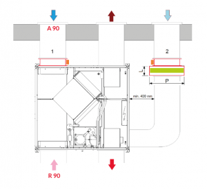
(1) outdoor air at -5°C 80% RH, ambient air at 20°C 50% RH; nominal air flow rate (2) outdoor air at 32° C 50% RH, ambient air at 26°C 50% RH; nominal air flow rate (3) with ventilation regulation signals and heat pump at the maximum permissible value

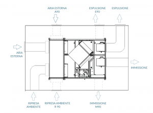
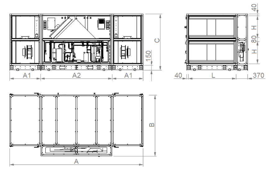
For each size, it is possible to adapt the fresh air and exhaust intakes to the system according to the configurations illustrated in the figure, even with unit already installed.

To change the position of the intakes simply exchange the filter panels with the corresponding panels.

The M90 configuration must necessarily be specified on the order as it involves exchanging the positions between the supply fan and the electrical panel, this operation that is not possible with the unit is already installed.

BPL EXTERNAL BY-PASS SYSTEM

A set of components installed (by the customer) outside the unit, required if the configuration of the unit is with M90 and E90 fans, able to create, commanded by the on-board electronics, an additional circuit of external air (free-cooling outdoor air) in direct communication with the supply fan.

This kit consists of:

  • Servomotor damper on the fresh air (1)
  • Ducted module on free-cooling air duct with servomotor (opposed to the previous one) and an high efficiency filter extractable from below.

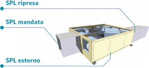
The table shows the sound power values (SWL) in octave band and the related results; the sound pressure values (SPL) at 1m, 5m and 10m in supply, in return and outside of the unit are also highlighted, under ducted unit conditions.


The graphs provide an indication of the useful static pressure (P a) as the airflow [m3/h] supplied by the base inlet unit varies. Consult the technical bulletin to check the specific data of the unit’s aeraulic performance.