Product Range

HRC

Heat recovery unit WITH HIGH EFFICIENCY HEAT RECOVERY FLEXIBILITY AND VERSATILITY DURING INSTALLATION
from 250 to 3,500 m³/h

Ventilation unit designed and built for non-residential applications, it enables to combine the need for air renewal with energy savings and maximum flexibility and versatility during installation, thanks to the 90° adjustable air intakes by moving the closing panels.
Equipped with aluminium plate heat recovery unit, fans with EC motors and integrated motorised by-pass system for free-cooling operation.
The series, fitted with a simple kit for vertical configuration, is divided into seven sizes, for air flows ranging from 250 to 3,500 m³/h.

 
  • Internal galvanised sheet supporting structure with 25 nominal mm thick sandwich panels in internally galvanised sheet and pre-painted externally in RAL 9002 finish; lower cross bars in galvanised steel for anchoring to the ceiling
    Non-flammable thermal and acoustic insulation in mineral wool
  • Static heat recovery unit with high efficiency of the counter flow air-to-air type with aluminium exchange plates fitted with additional sealing, integrated with an already motorised by-pass system. Aluminium condensate collection tank with 1/2” F dual bottom drain
  • Compact filters with synthetic media (external layer) and fiberglass (internal layer) and galvanised steel frame, efficiency class ePM10 50% on room intake and ePM1 50% on outdoor air intake, removable at the bottom. Each filtering station is already equipped with a control pressure switch wired to the panel and suitable for housing two filters in sequence
  • Centrifugal fans with free-running impeller with backward blades directly coupled to EC technology electric motors
  • Set-up for electric heating element
  • Set-up for post-heating electric heating element or for water coil.
  • Recessed type electrical panel with electronic adjustment and remote user interface for complete control of all the key functions and specifically :
    - manual control of the EC fans
    - automatic control of the fans (for pressure, temperature or air quality)
    - modulating control of the water valve (mixed use)
    - electric heater management (pre and post)
    - recovery unit defrosting management
    - free-cooling on/off management
    - post-ventilation
    - weekly programming
    - alarm management and clogged filter warning
    - remote on/off
    - remote summer/Winter
    - fan and damper management via fire alarm digital input
    - BMS via Modbus protocol and RS485 connection. 


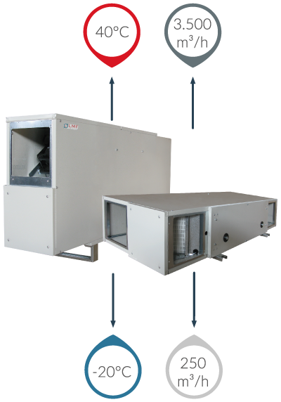
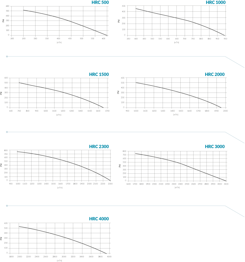
(1) referred to nominal flow rate (2) inlet air at 28°C/60%UR; water in/out 7°/12°C (3) inlet air at 13°C/; water in/out 45°/40°C
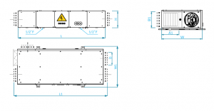
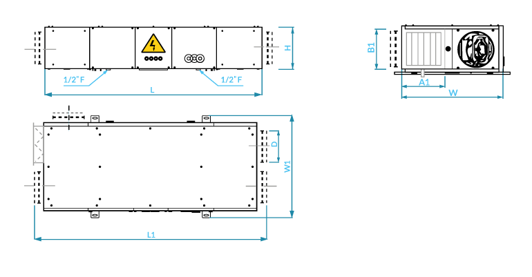
Two air flow configurations are available, a “right” and a “left” one, both referring to the view of the electrical panel: With the first, the inlet fan (and therefore the aeraulic connection for the supply to the rooms to be treated) is located to the right of the electrical panel. All other air intakes are therefore uniquely determined. 
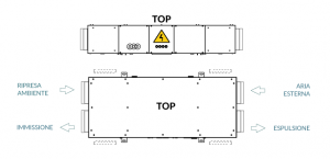
With the second, the inlet fan (and therefore the aeraulic connection for the supply to the rooms to be treated) is located to the left of the electrical panel. All other air intakes are therefore uniquely determined All air intakes can still be adjusted by 90° by moving the side end closing panels, even in the installation site. The KTV conversion kit does not change the aeraulic structure defined above. 
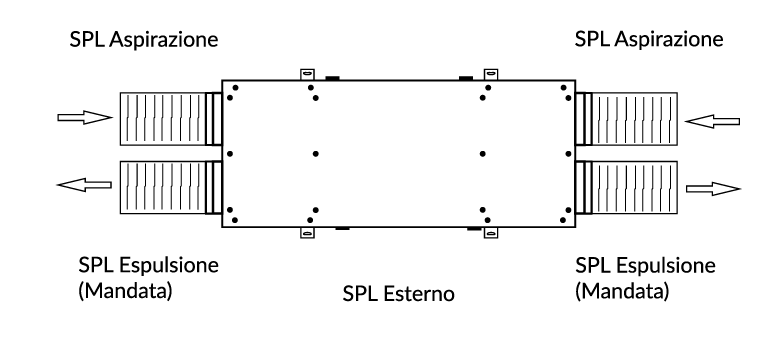
With reference to the nominal operating conditions and balanced flow rates, the following table shows the sound power values (SWL) in octave and total bands. The sound pressure levels (SPL) at 1m, 5m and 10m in supply/exhaust, outdoor air/return and outside the unit, in ducted unit conditions are also indicated.

The graphs provide an indication of the useful static pressure (Pa) as the airflow [m 3/h][m3/h] supplied by the base inlet unit varies. Consult the technical bulletin to check the specific data of the unit's aer aulic performance.